The $100 Temp Controlled and Filtered Printer Enclosure
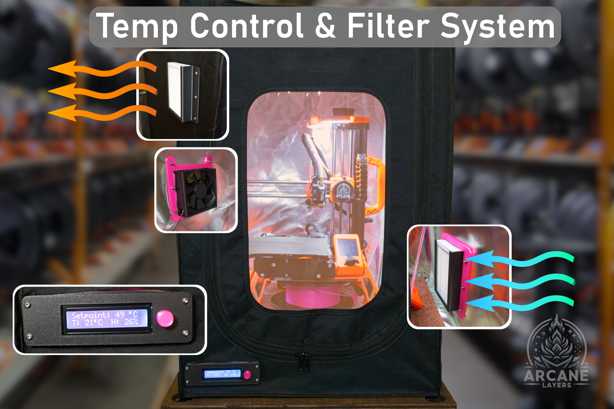
Imagine transforming your 3D printing experience with a DIY enclosure upgrade that costs just $100. This transforms your enclosure into a temperature-controlled and air-filtered system, ensuring your prints come out perfect every time, and your lungs breath cleaner air. Whether you're a seasoned maker or a curious beginner, this project will walk you through the steps to create a professional-grade enclosure without breaking the bank. Ready to elevate your 3D printing game? Let's dive in!
This post contains affiliate links, any link marked with ¹ is an affiliate link. Using these links helps support my work!
What You'll Need
Purchase or find everything in the list below to get started
Everything you need for the Arduino is included in the Elegoo Super Starter kit. You do need a couple of extras such as the fans, ac, adapter, filters, and mini breadboard.
For this project almost any 3D printer enclosure will work, as long as you can cut holes in the side. Don't have an enclosure yet? Linked below is the enclosure I used for my project, that brings the total for the project to ~$150.
| Item | Optional? | Price | Link |
|---|---|---|---|
| Elegoo Arduino Super Starter Kit | No | ~$45 | Amazon¹ |
| 12V 80mm DC Fan | No | ~$7 | Amazon¹ |
| HEPA Filters | No | ~$12 | Amazon¹ |
| Mini Breadboard | No | ~$6 | Amazon¹ |
| M3 Screws and Nuts | No | ~$7 | Amazon¹ |
| AC to DC Adapter 12V | No | ~$10 | Amazon¹ |
| PLA Filament | Sorta | ~$5 (Material Cost) | Amazon¹ |
| 3D Printer Enclosure | Yes | ~$39 | Amazon¹ |
| 5V 25mm DC Fan | Yes | ~$9 | Amazon¹ |
The list above includes my affiliate links for each product, using these helps support my work and allows me to continue making cool projects for free!
The Prints
Head to Printables.com to download and print all of the models. I recommend printing in PLA so that everything fits correctly, other materials will work but the fit may be looser or tighter then intended.
Recommended Print Settings:
- Layer Height: 0.2mm
- Infill: 15%
- Supports: None
- Material: PLA recommended, this model is designed for a tight fit, other materials may not work. I used Prusament Galaxy Black¹.
The Schematic
For experienced builders who don't need a step-by-step guide
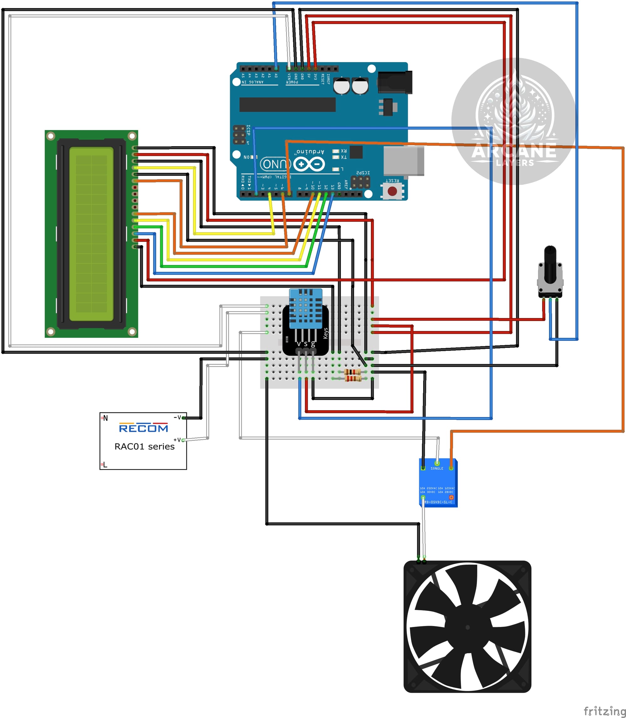
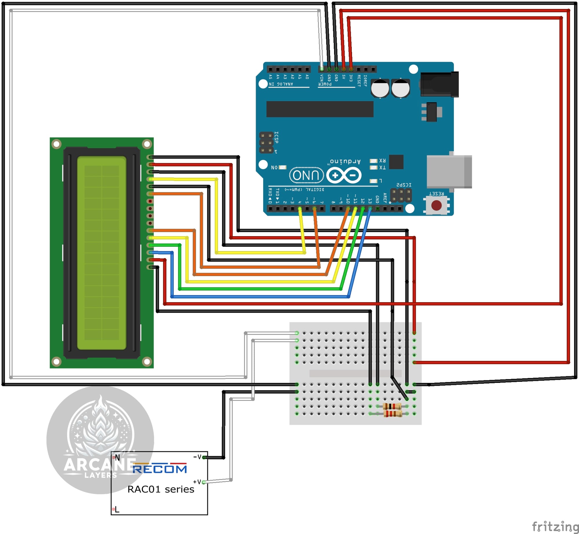
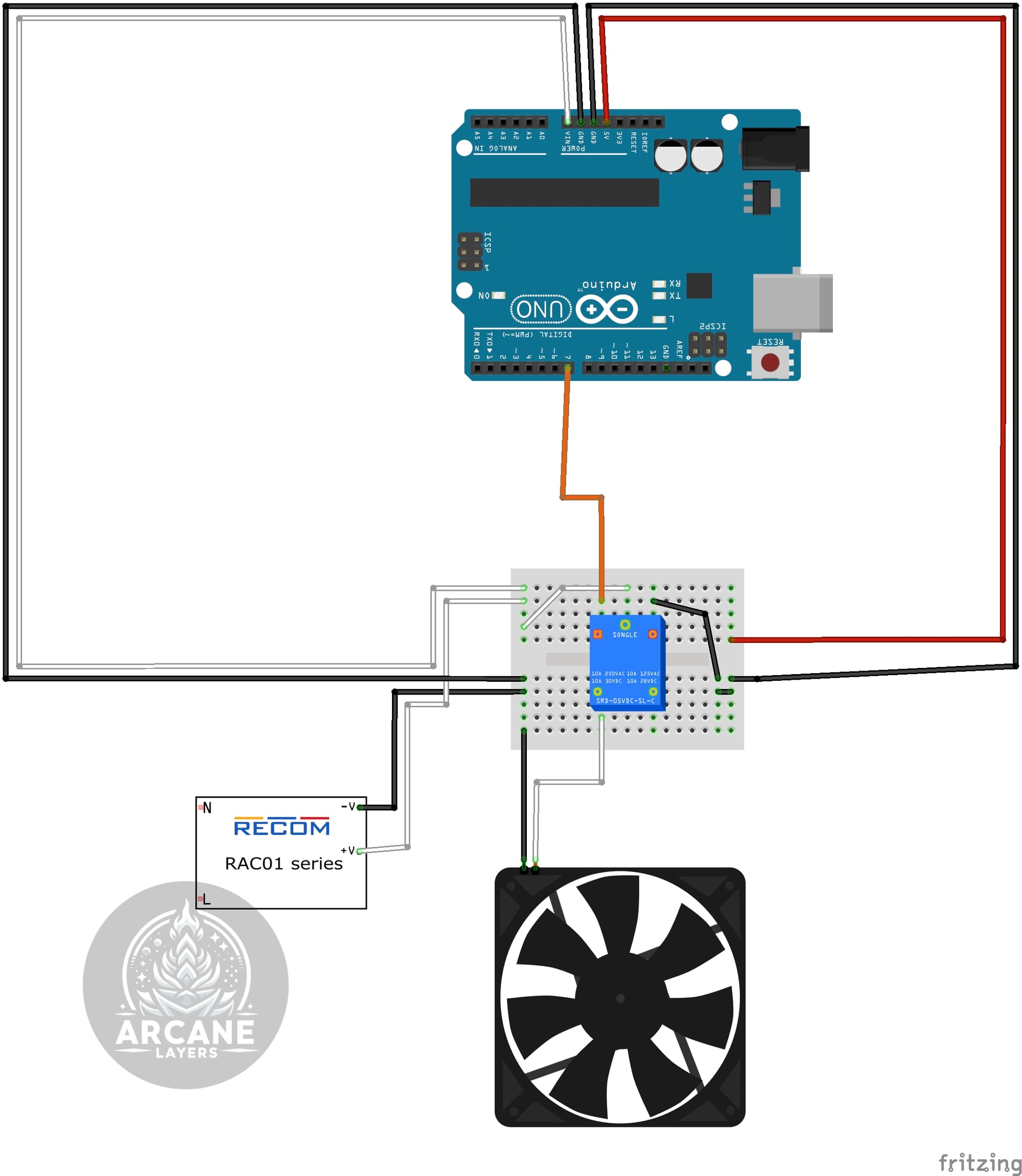
If you don't need the step by step tutorial, here is the full schematic. For clarity, the relay was moved off the mini breadboard, in the final build it should be on the breadboard.
Building the Controller Step-by-Step
-
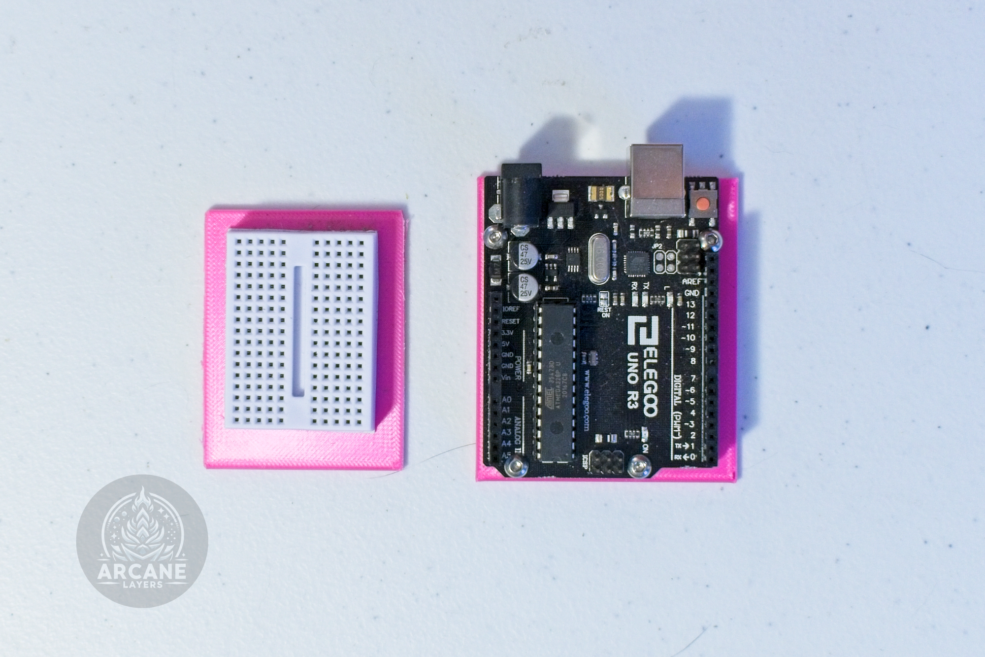
Screw the Arduino into its sled and stick the mini breadboard onto its sled.
-
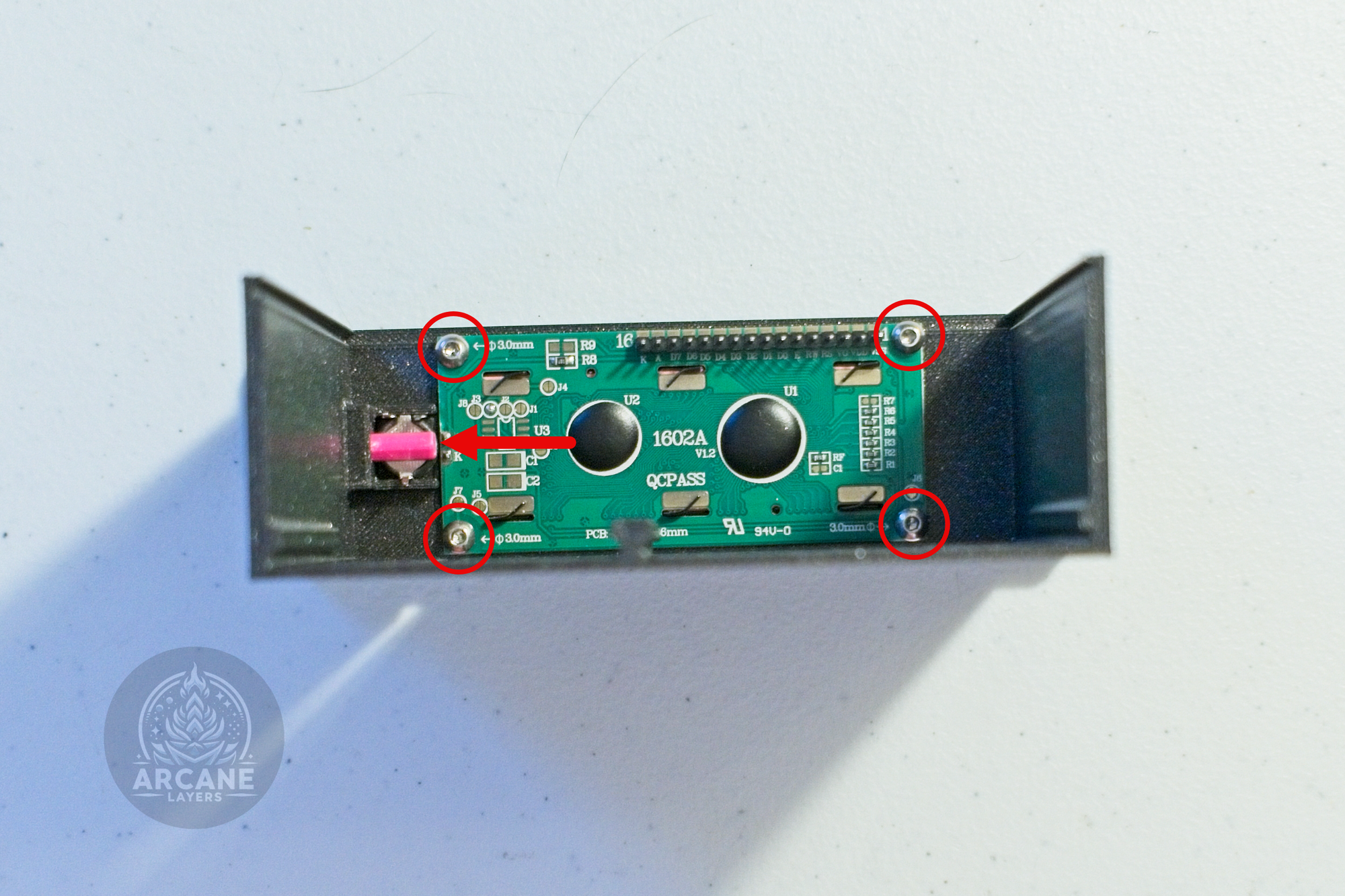
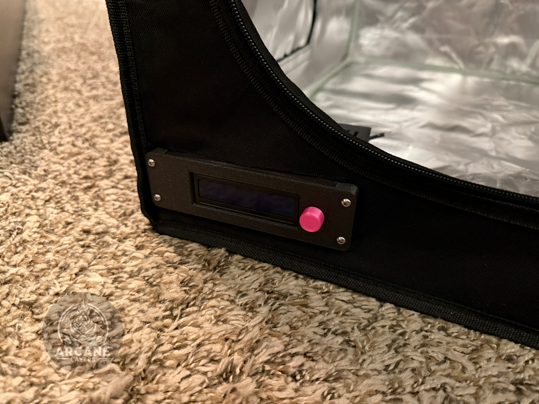
Screw the LCD into the Enclosure with (4x) M3x4mm screws, then place the potentiometer in place, and slide the retention bar into the slot to hold the potentiometer.
-
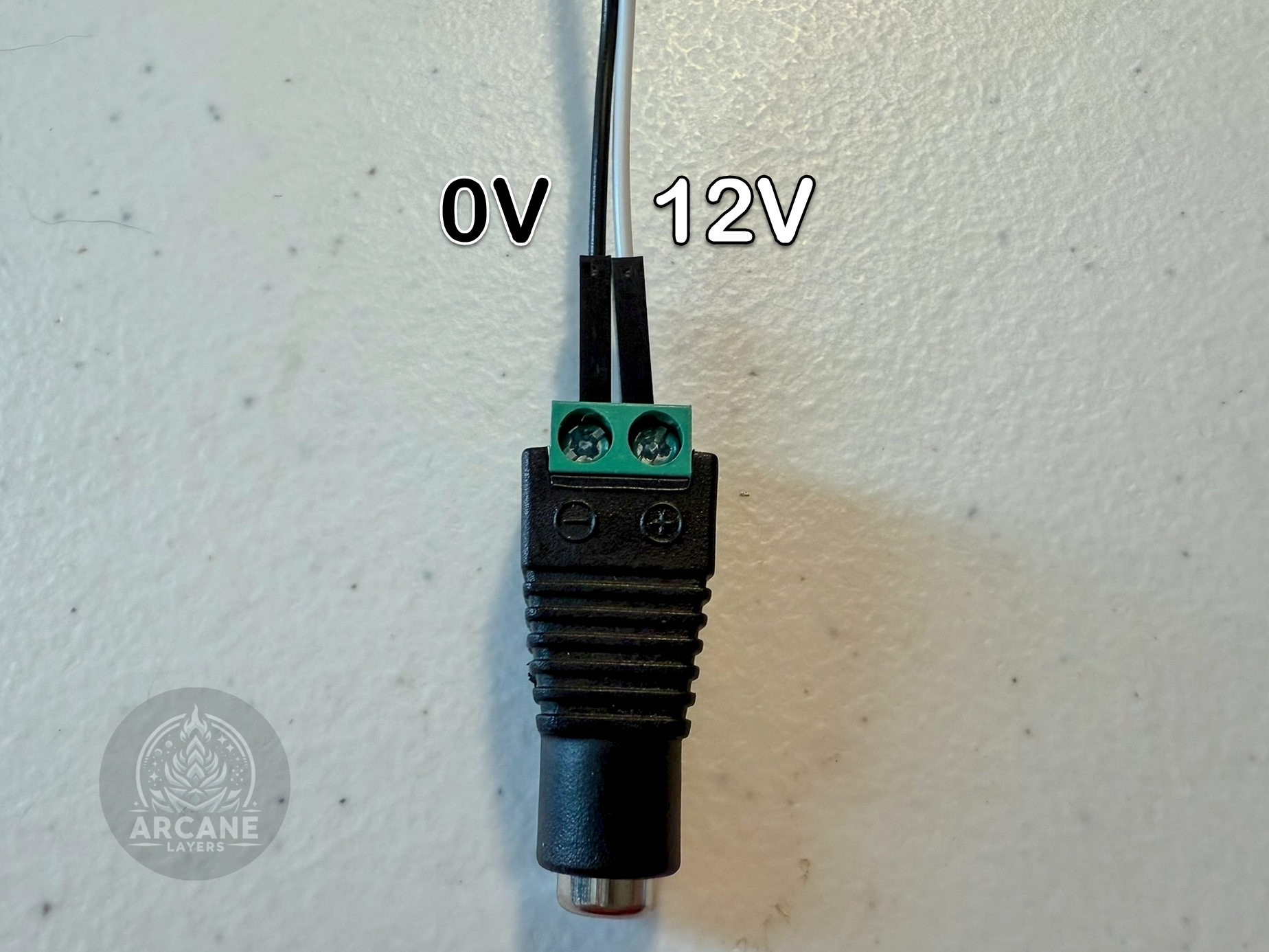
Next, take the barrel adapter which comes with the power supply and screw two wires into it, I will use white to indicate 12V and black to indicate 0V.
-
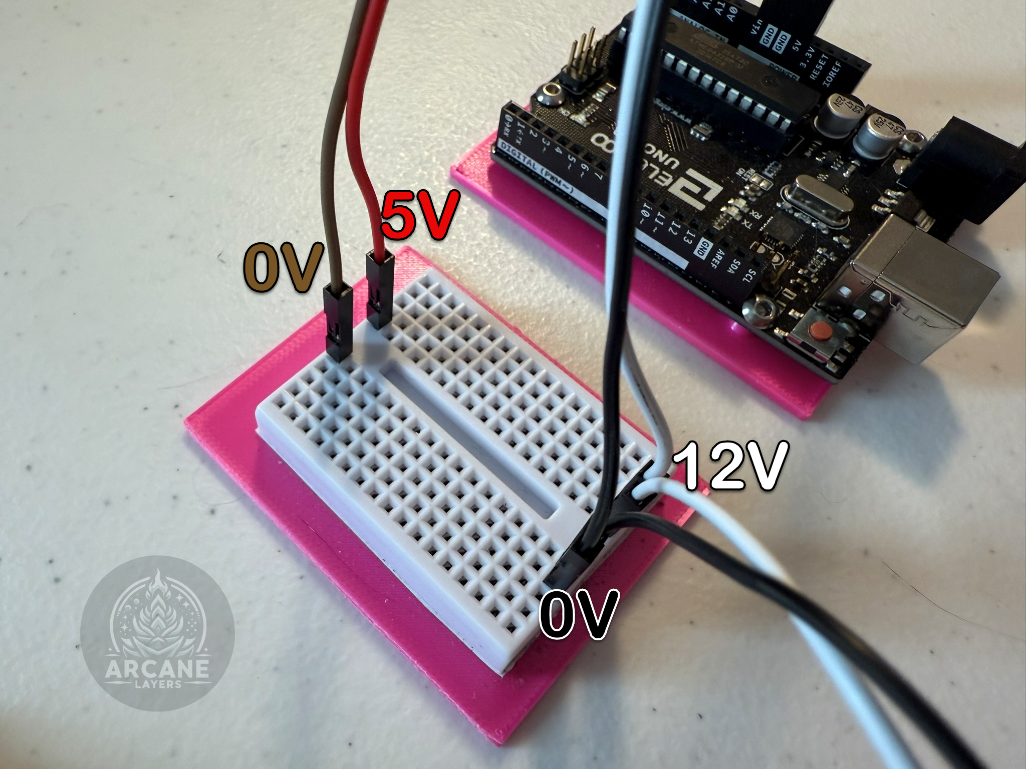
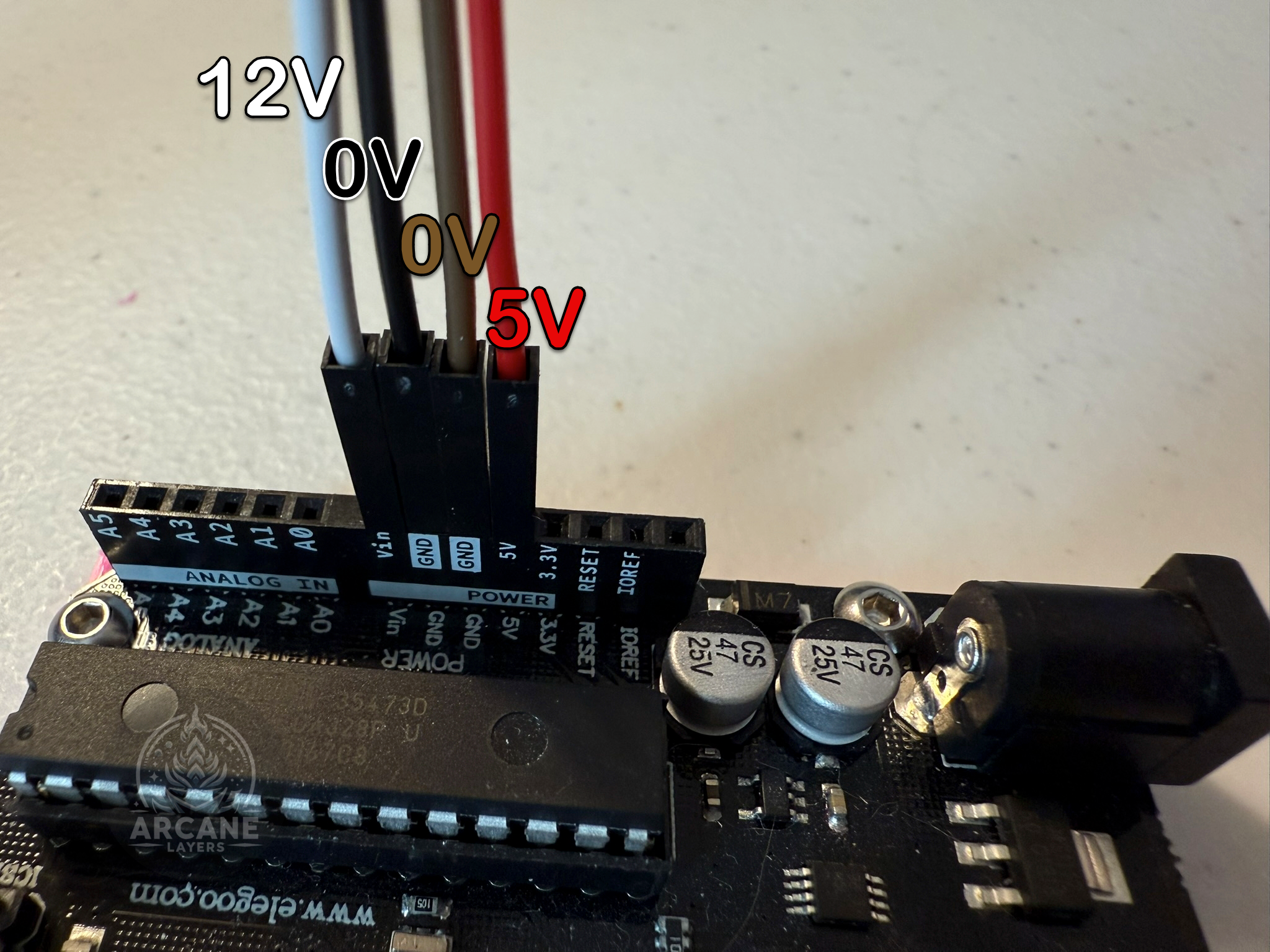
Run the wires into the bread board on two different rows, then run the 12V to the V_in on the Arduino, and the 0V to the GND pin on the Arduino. Then run wires from the 5V and GND on the Arduino back to the breadboard on two different rows from the first.
-
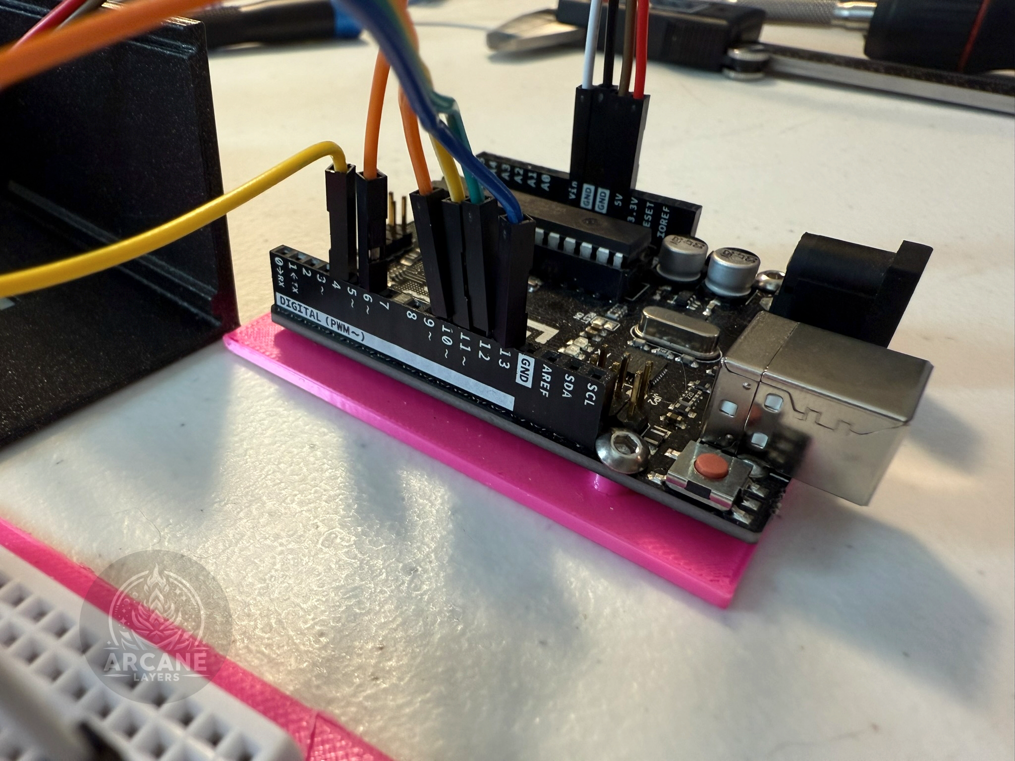
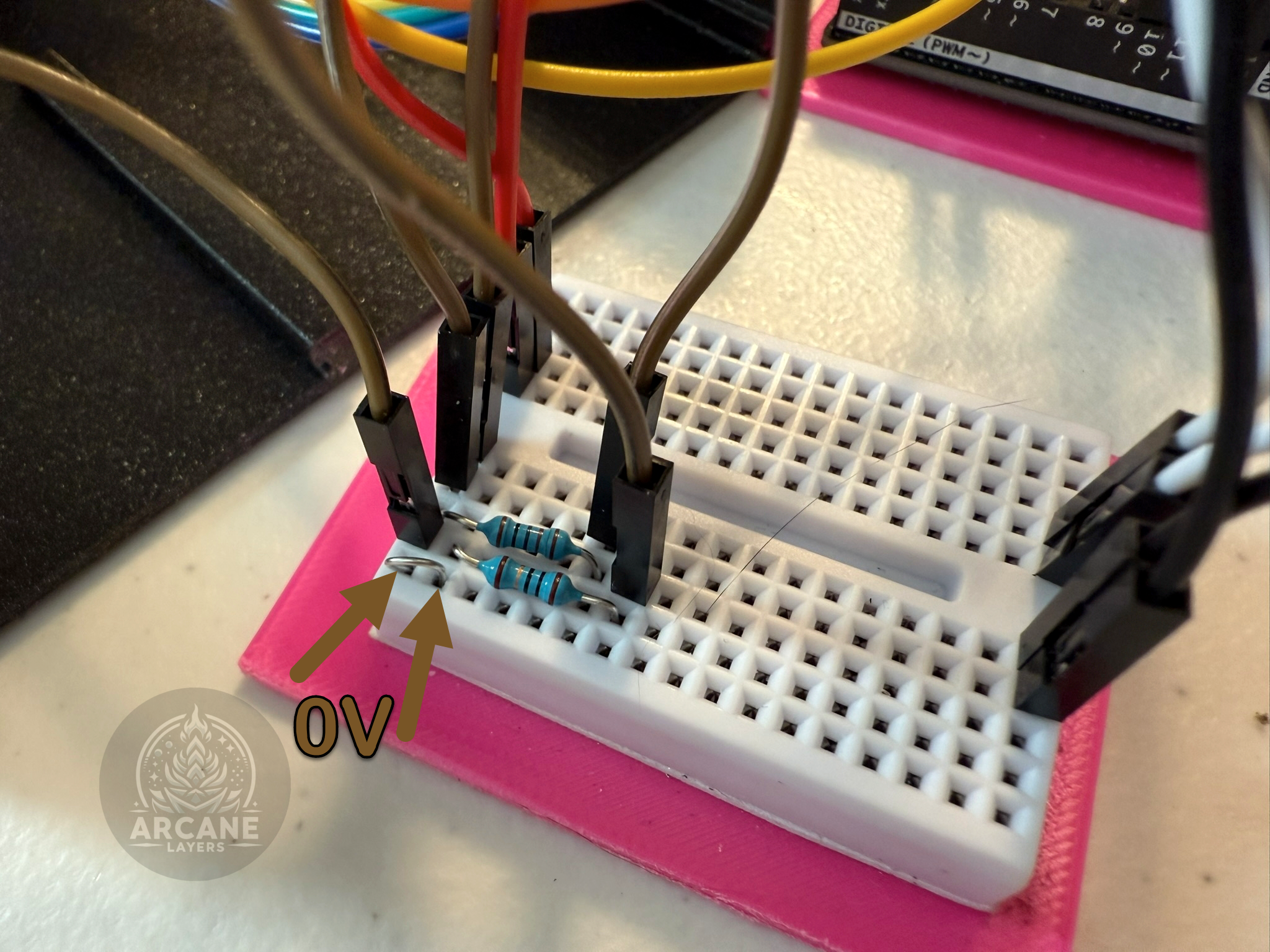
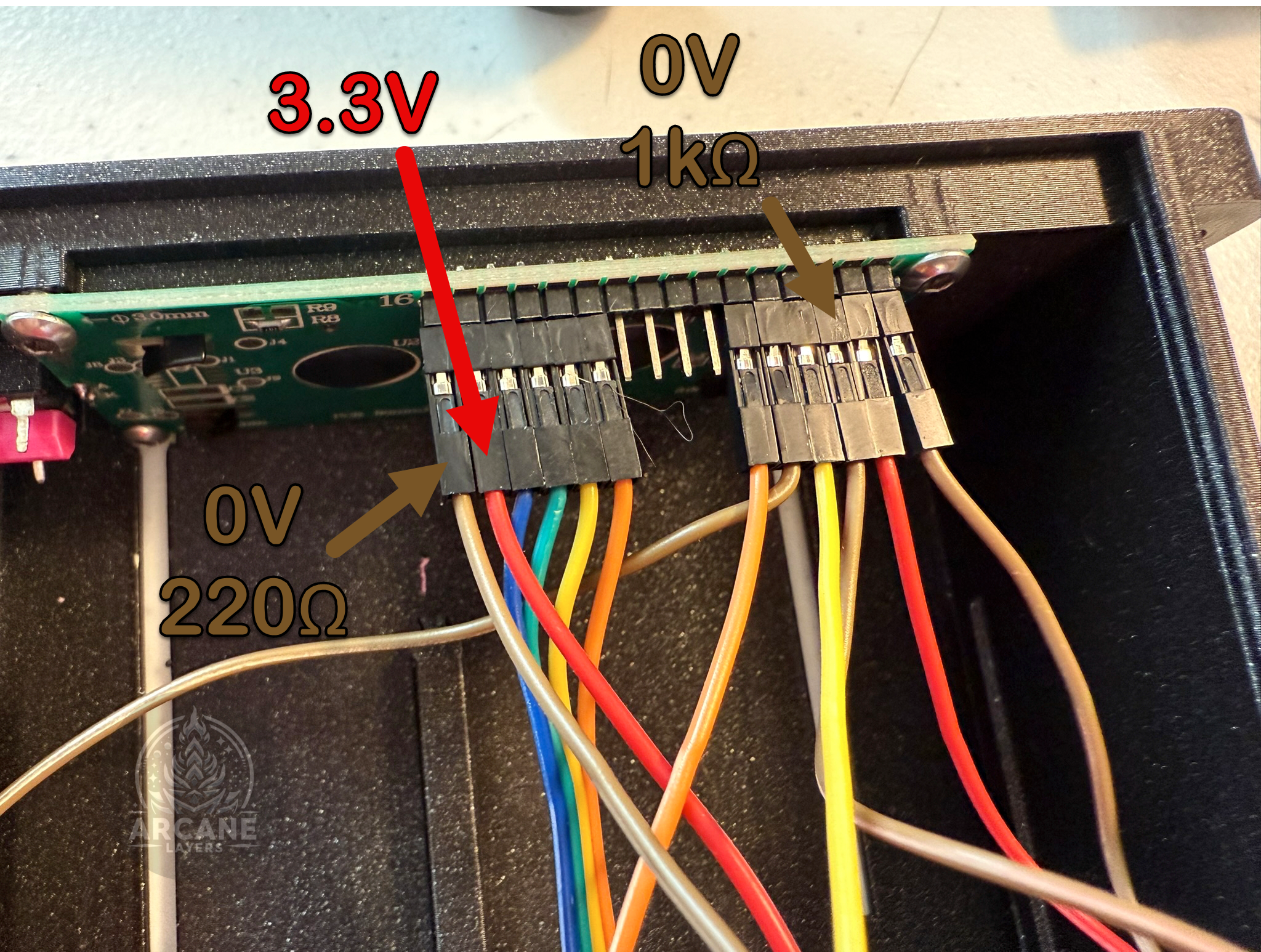
Next wire in the LCD according to the diagram below. The resistor on the top is 220Ω, and the resistor on the bottom is 1kΩ.
-
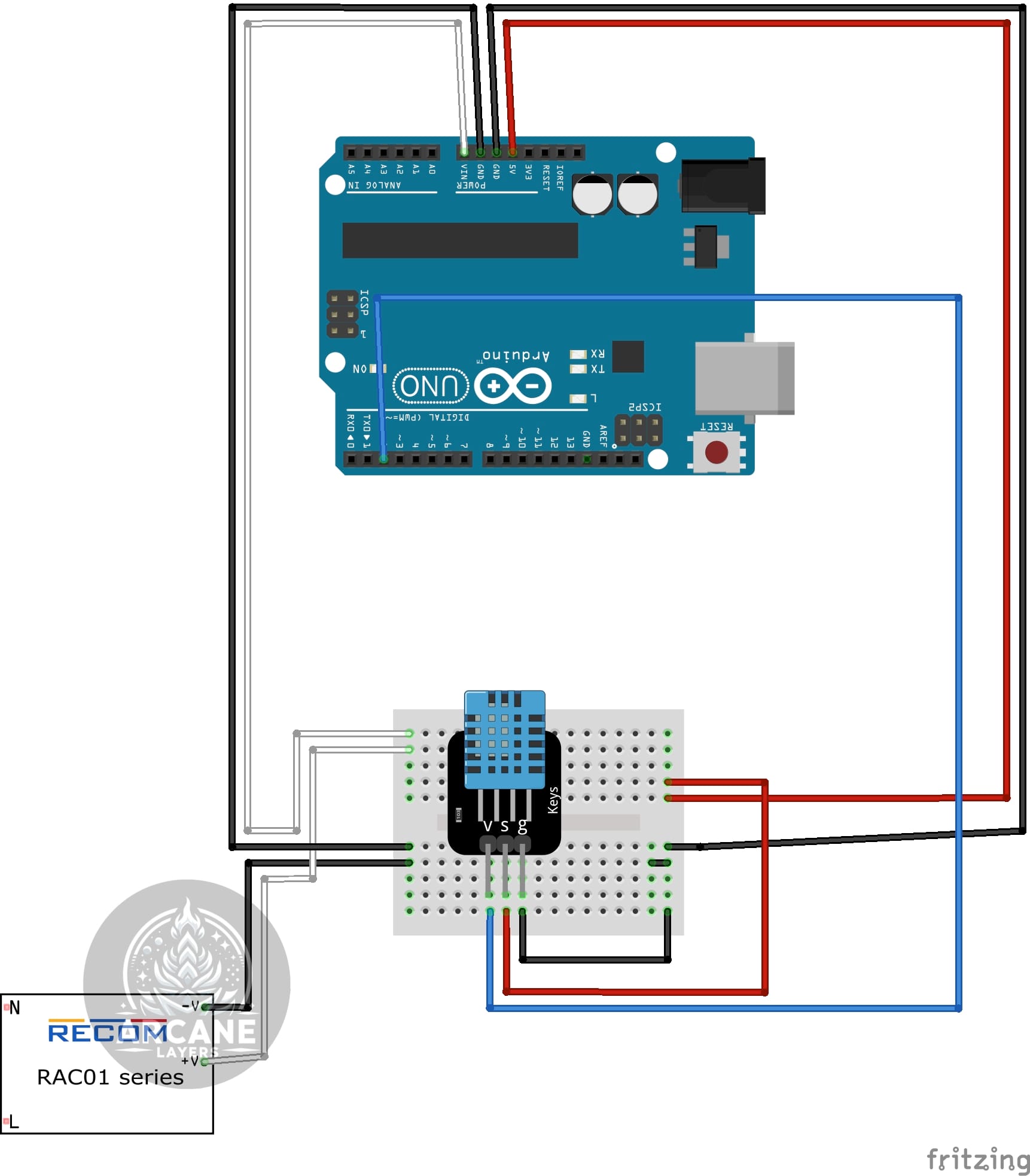
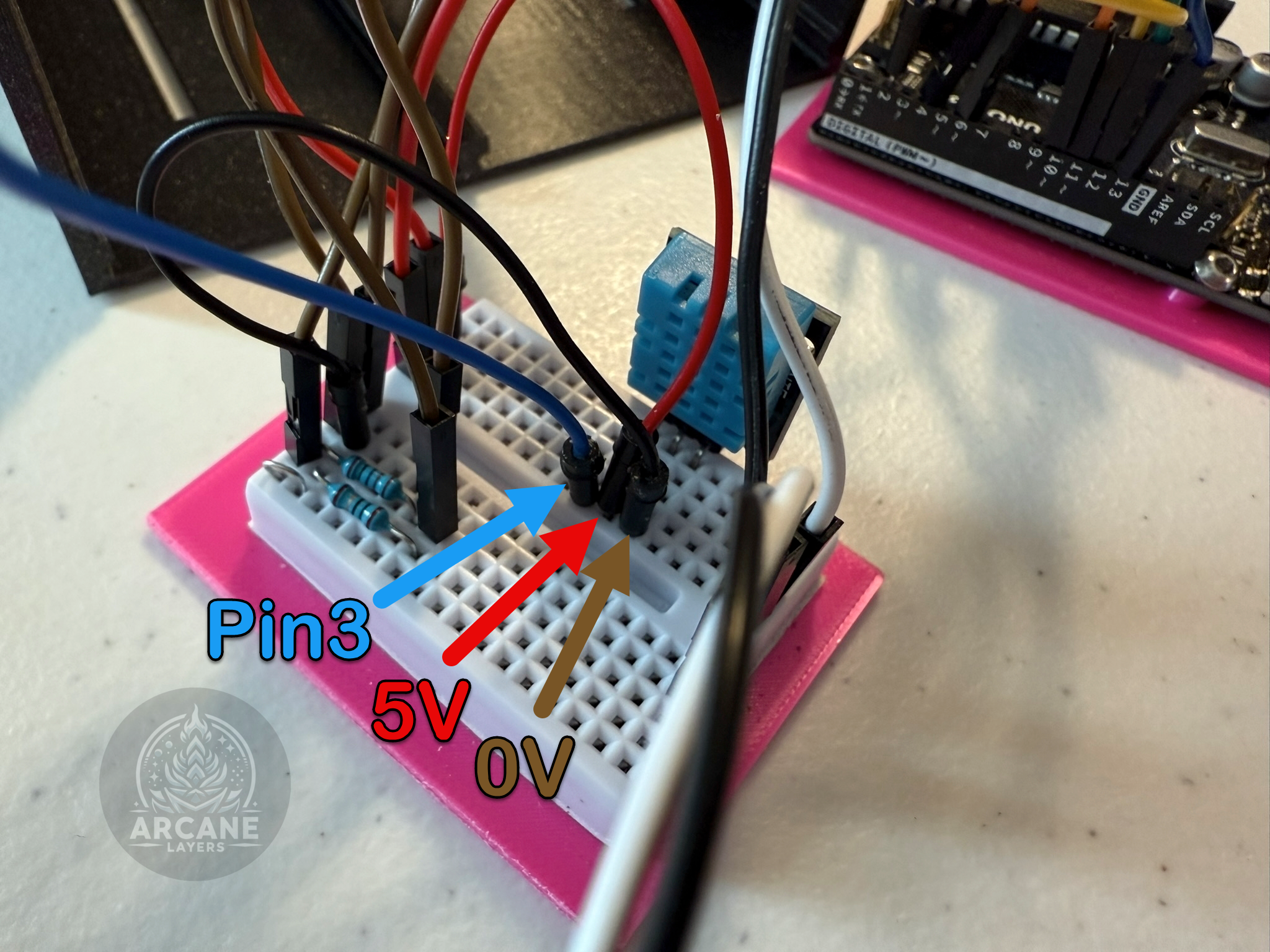
Wire the DHT in by following the diagram below. It should be connected to 0V, 5V, and Pin 2.
-
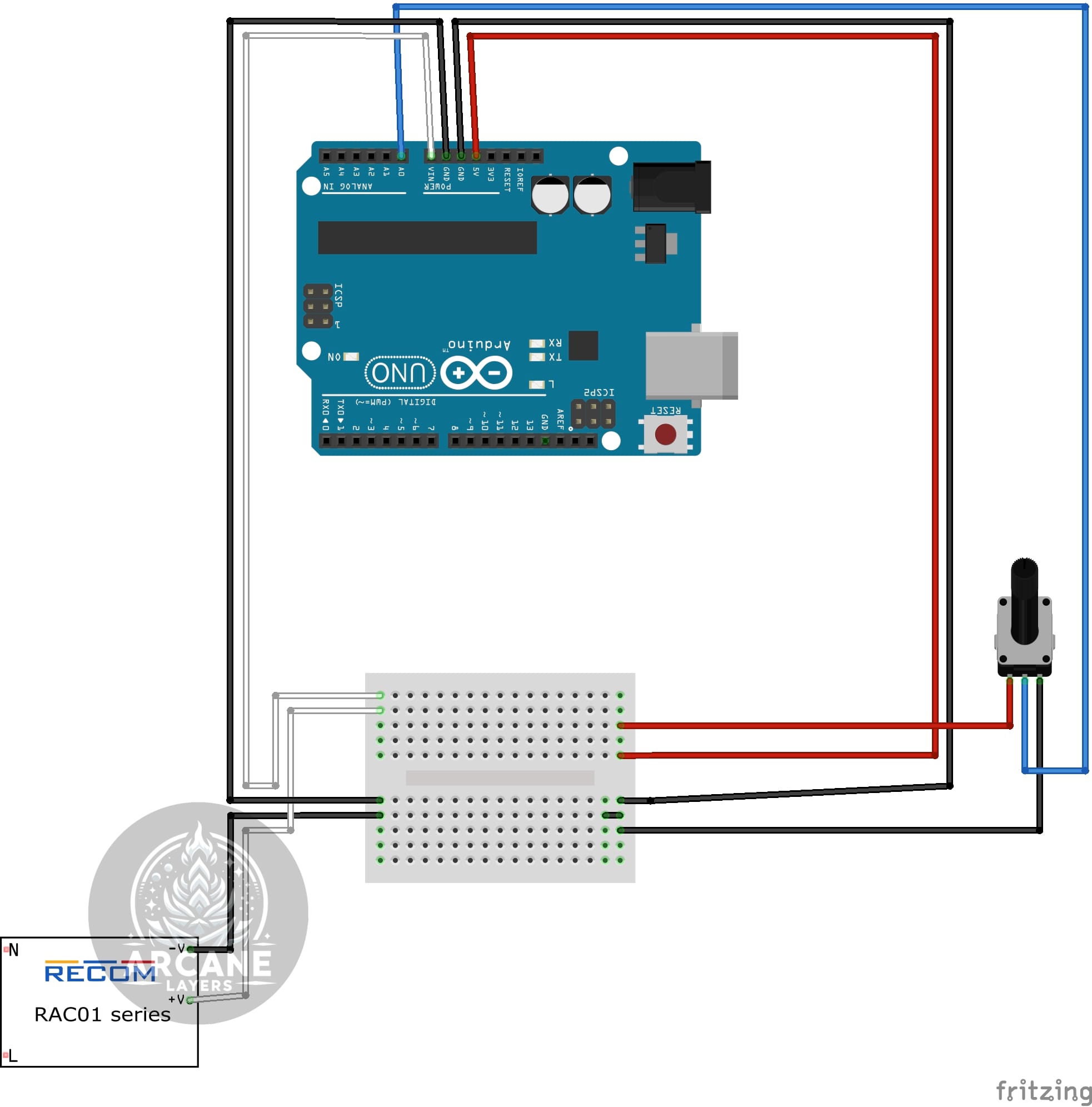
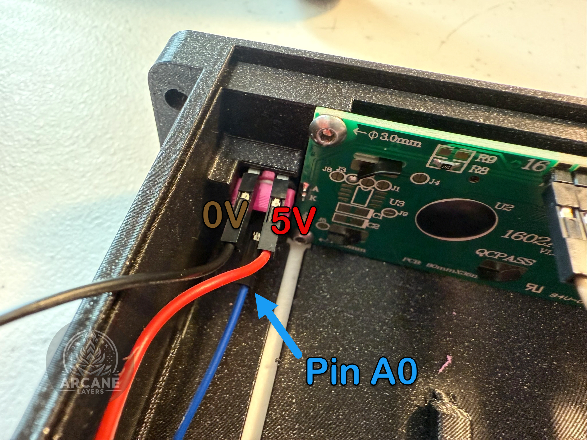
Wire the potentiometer by running 0V and 5V to the pins that are next to each other, then connect the pin on its own to A0, see the diagram below.
-
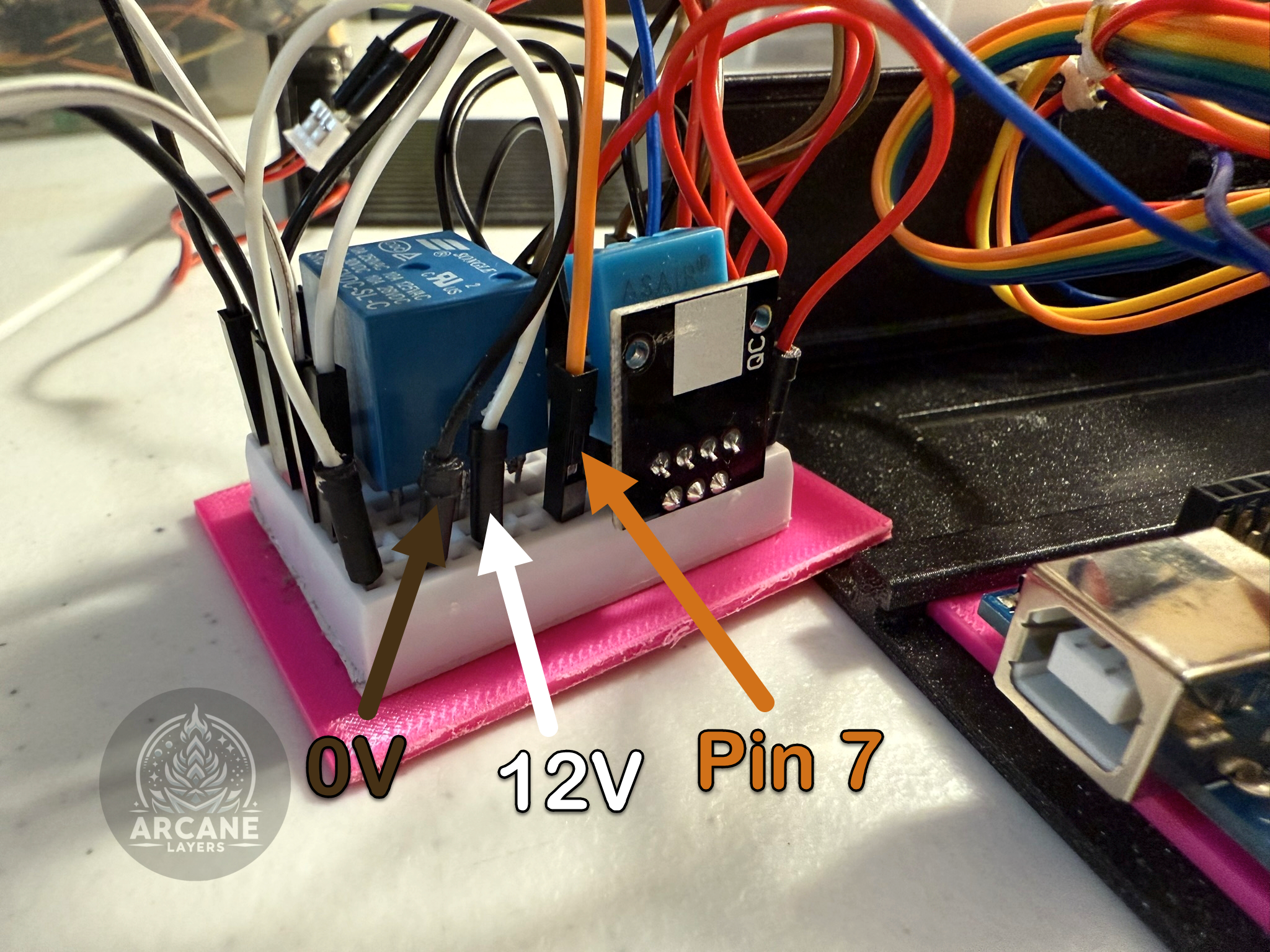
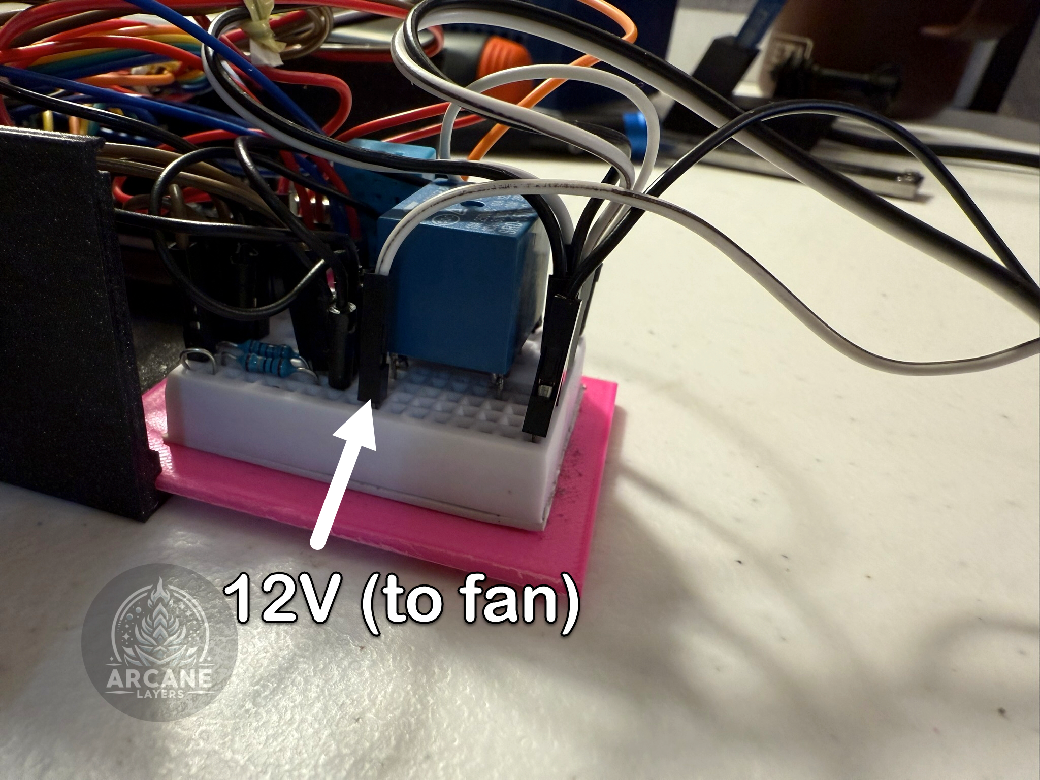
Wire in the relay, on the side with three pins, connect the top pin to 7 on the Arduino, the middle to 12V, and the lower to 0V. On the other side connect the bottom pin to the 12V side of the fan, then connect the fan back to 0V. See the diagram below. You can most likely stick the wires into the fans connector.
-
At this point everything is wired! Upload the code to the Arduino via USB in the next step!
Programming the Arduino
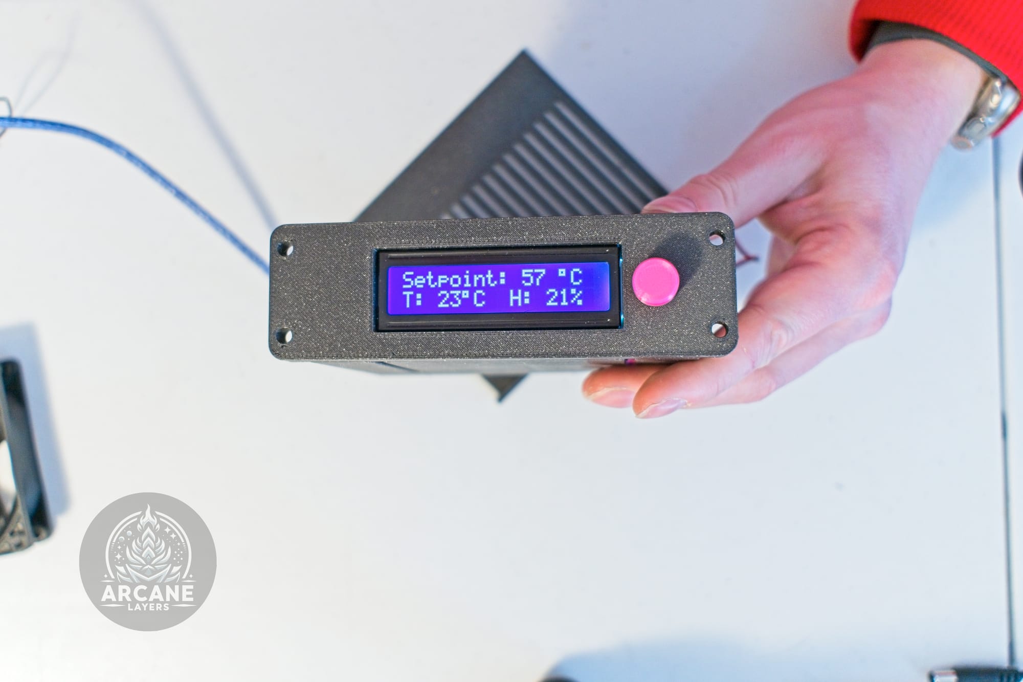
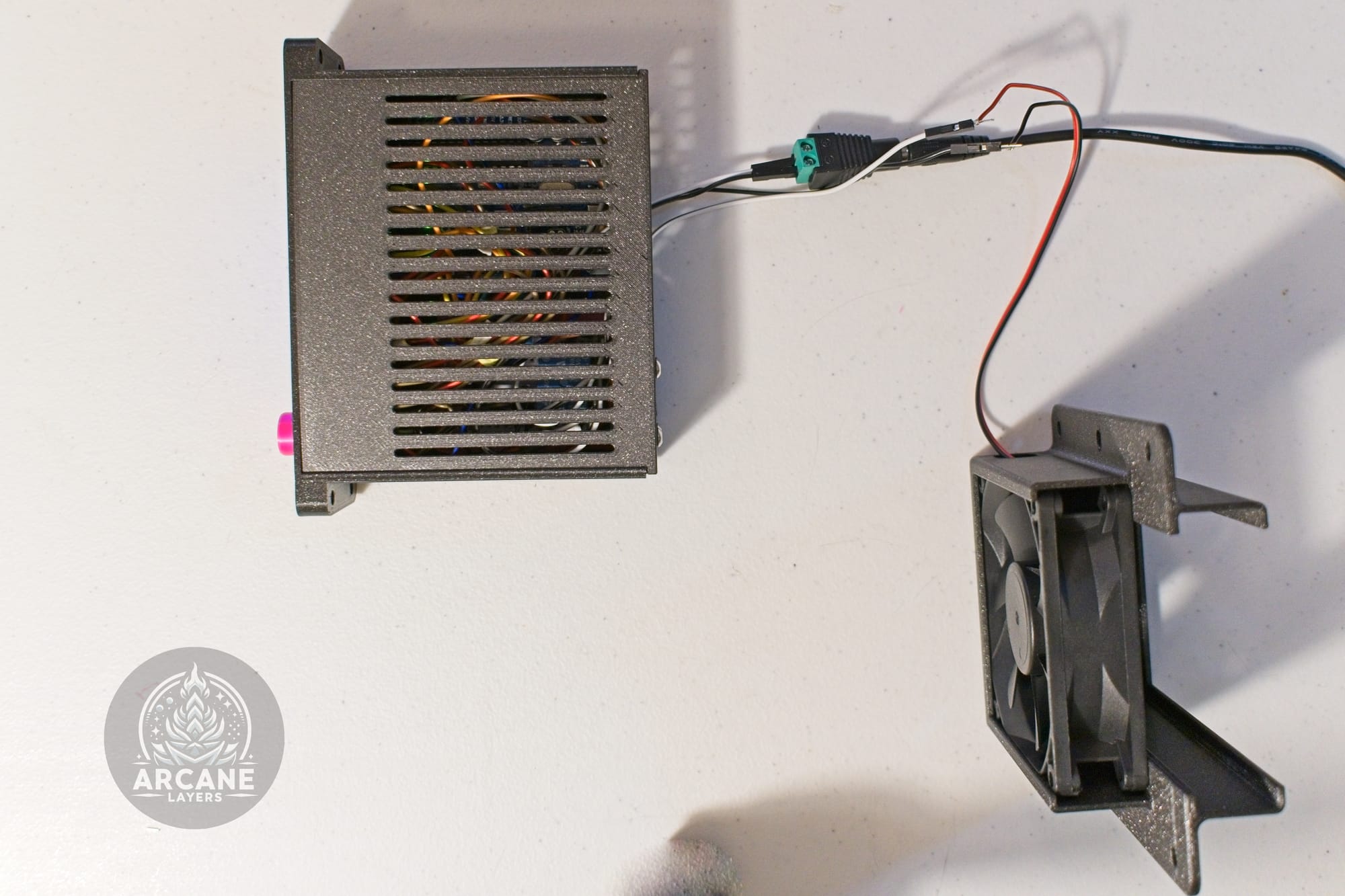
Once your controller is assembled, its time to program the Arduino. Download the Arduino sketch from GitHub, and upload the code to the Arduino using your computer. Verify the display works, the setpoint changed with the potentiometer, the temperature read-out is good, and the fan turns on and off based on the setpoint.
Building The Enclosure
Before building the enclosure, make sure you have all of the parts printed, everything on hand, and the controller built and tested.
Ideally the intake should go at the bottom, the fan module at top, and controller where ever it fits best.
-
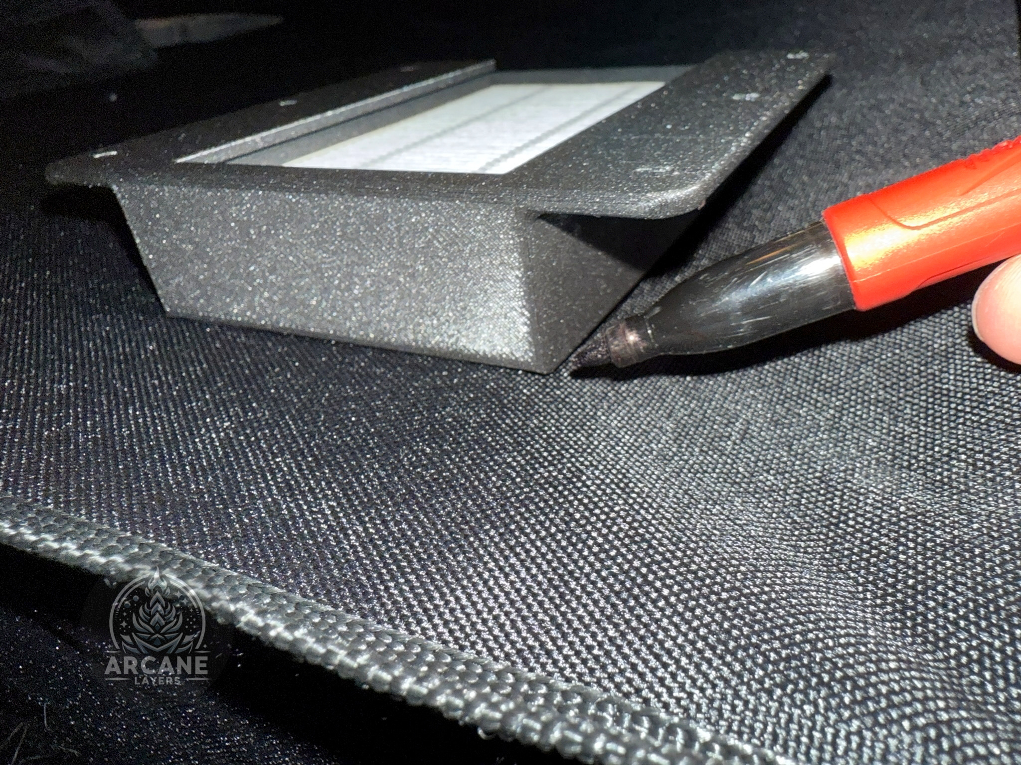
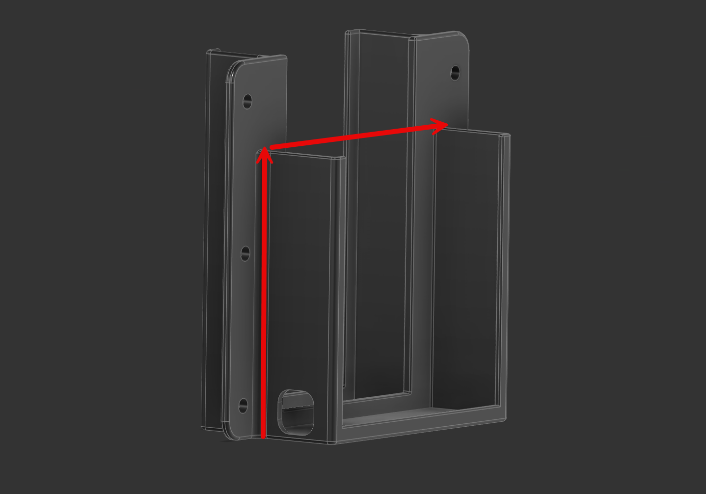
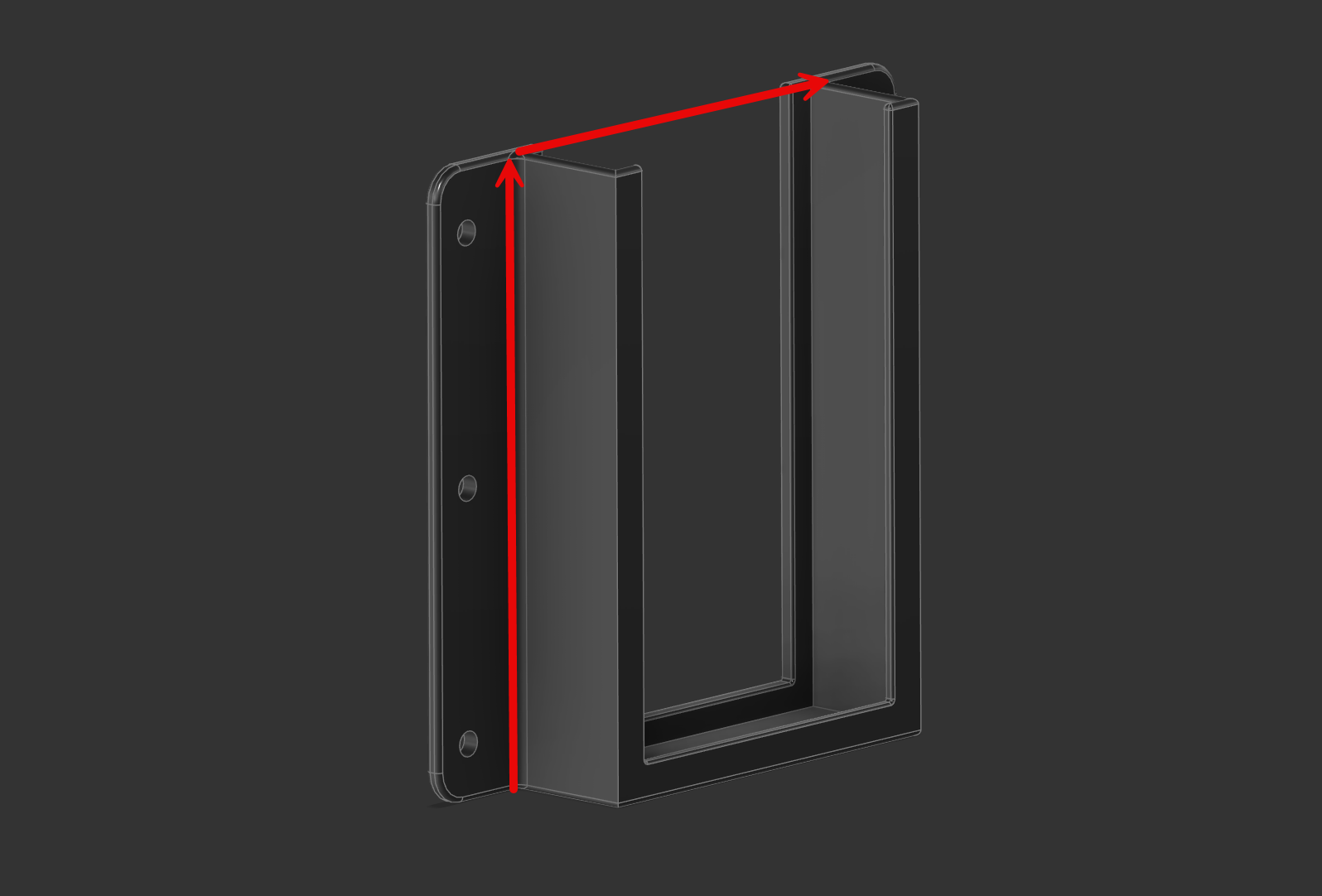
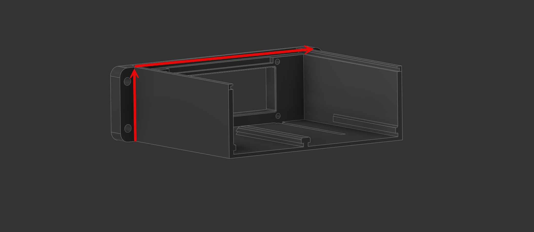
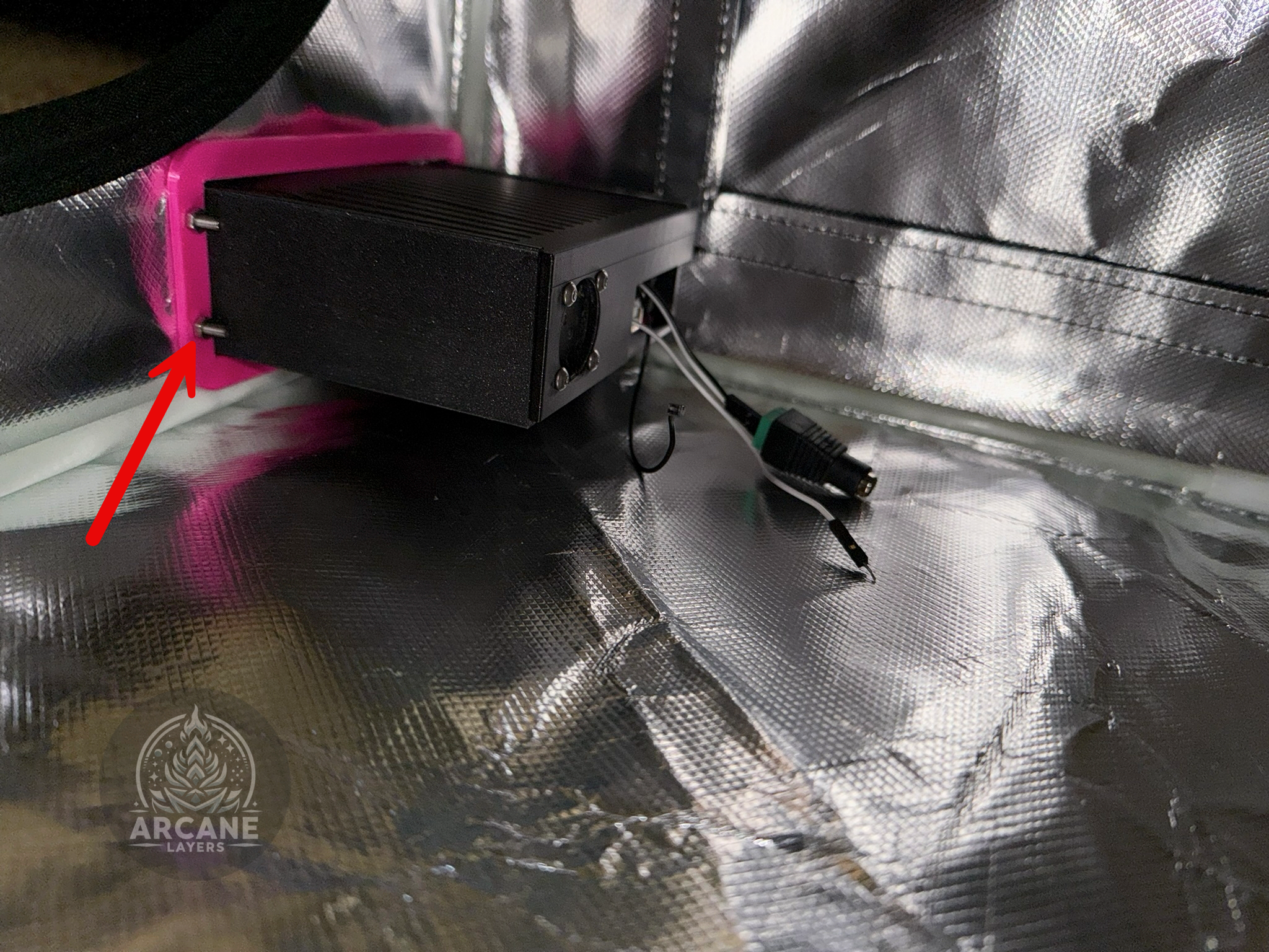
Trace a hole around each of the three parts that need to be punched into the enclosure using a permanent marker. For the controller, trace around the enclosure's main box, for the filter, trace around the part that holds the filter, and for the fan, trace around the part that holds the fan.
-
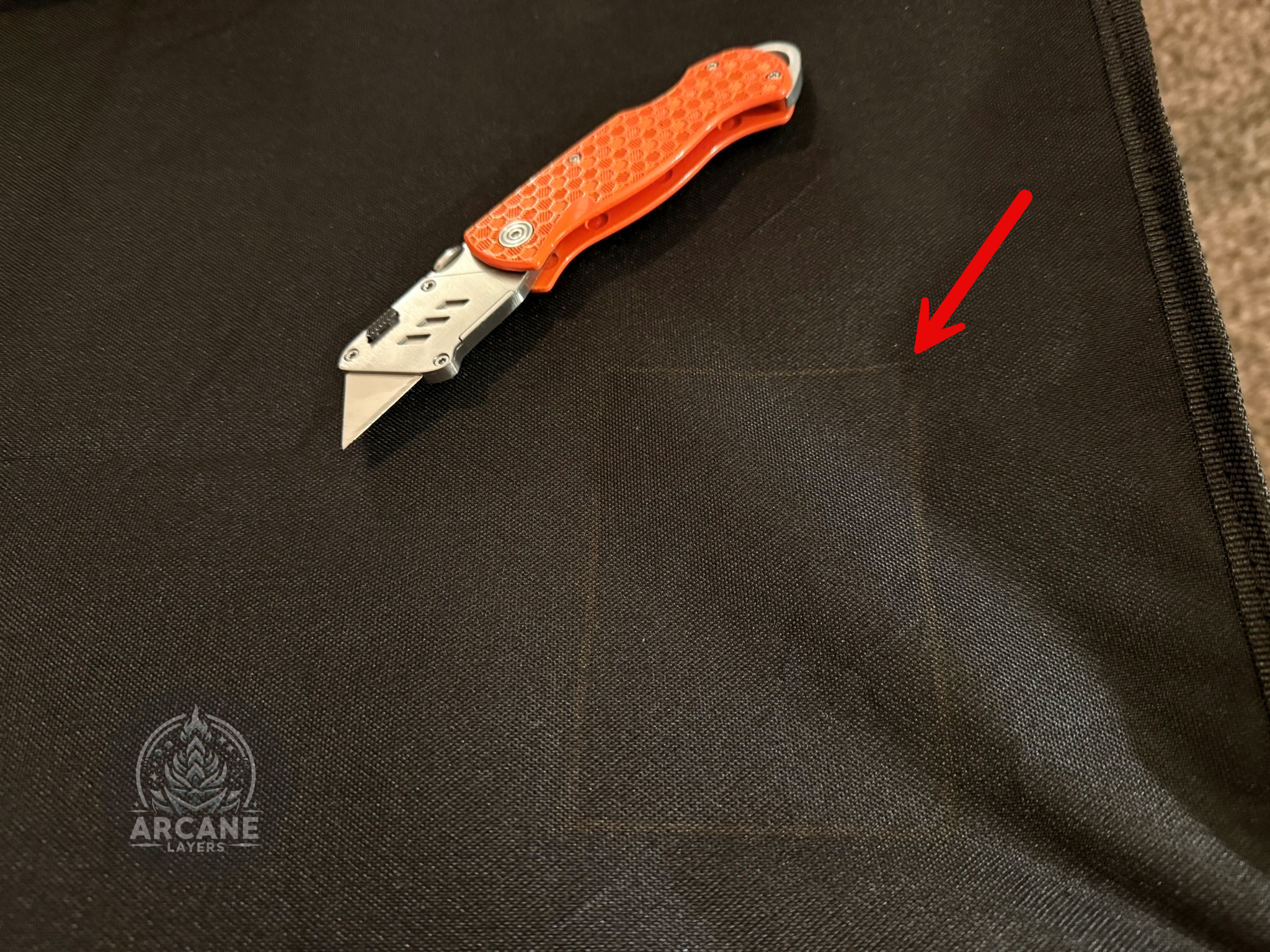
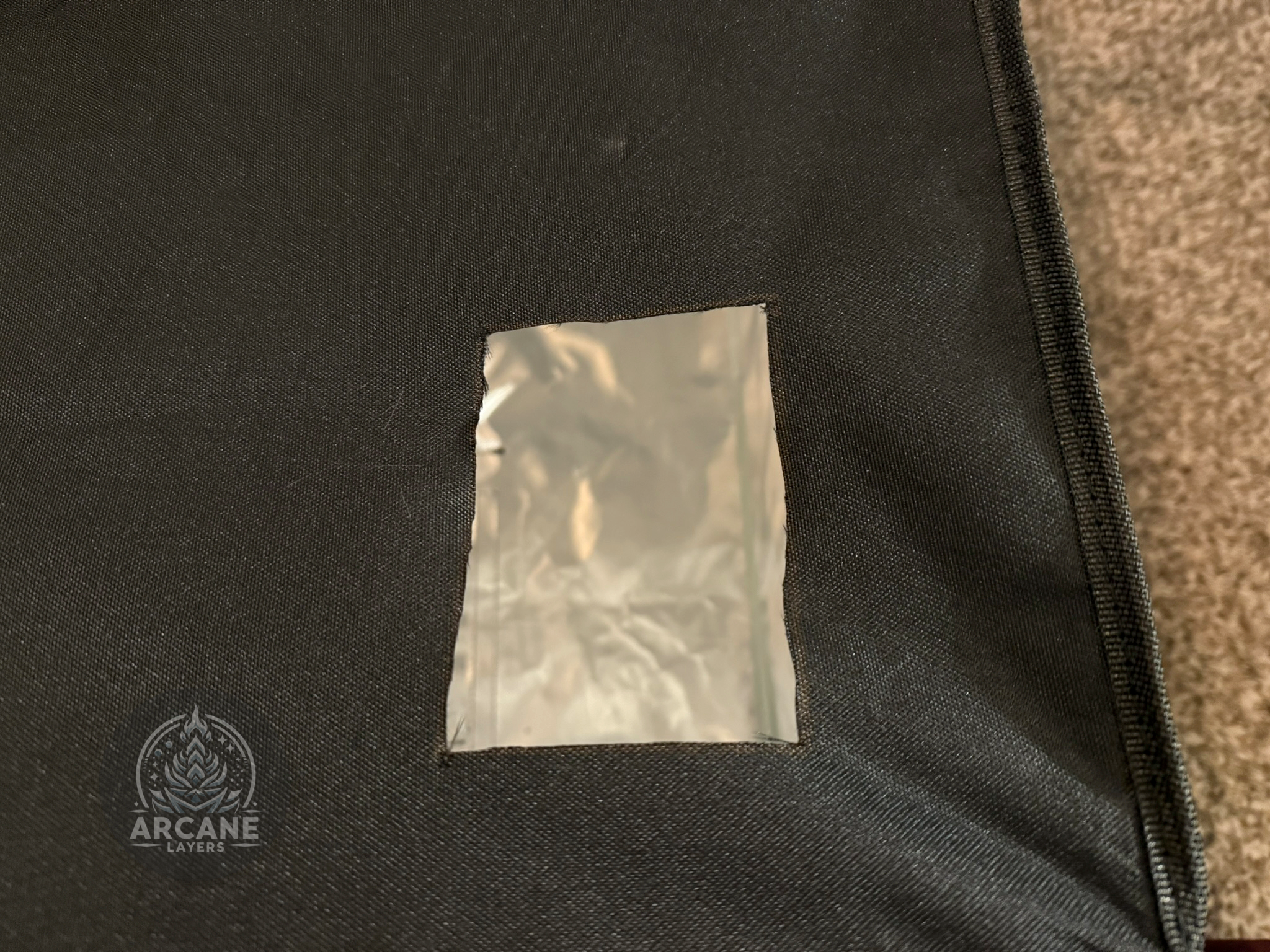
Use a utility knife or whatever suites your enclosure to cut the hole.
-
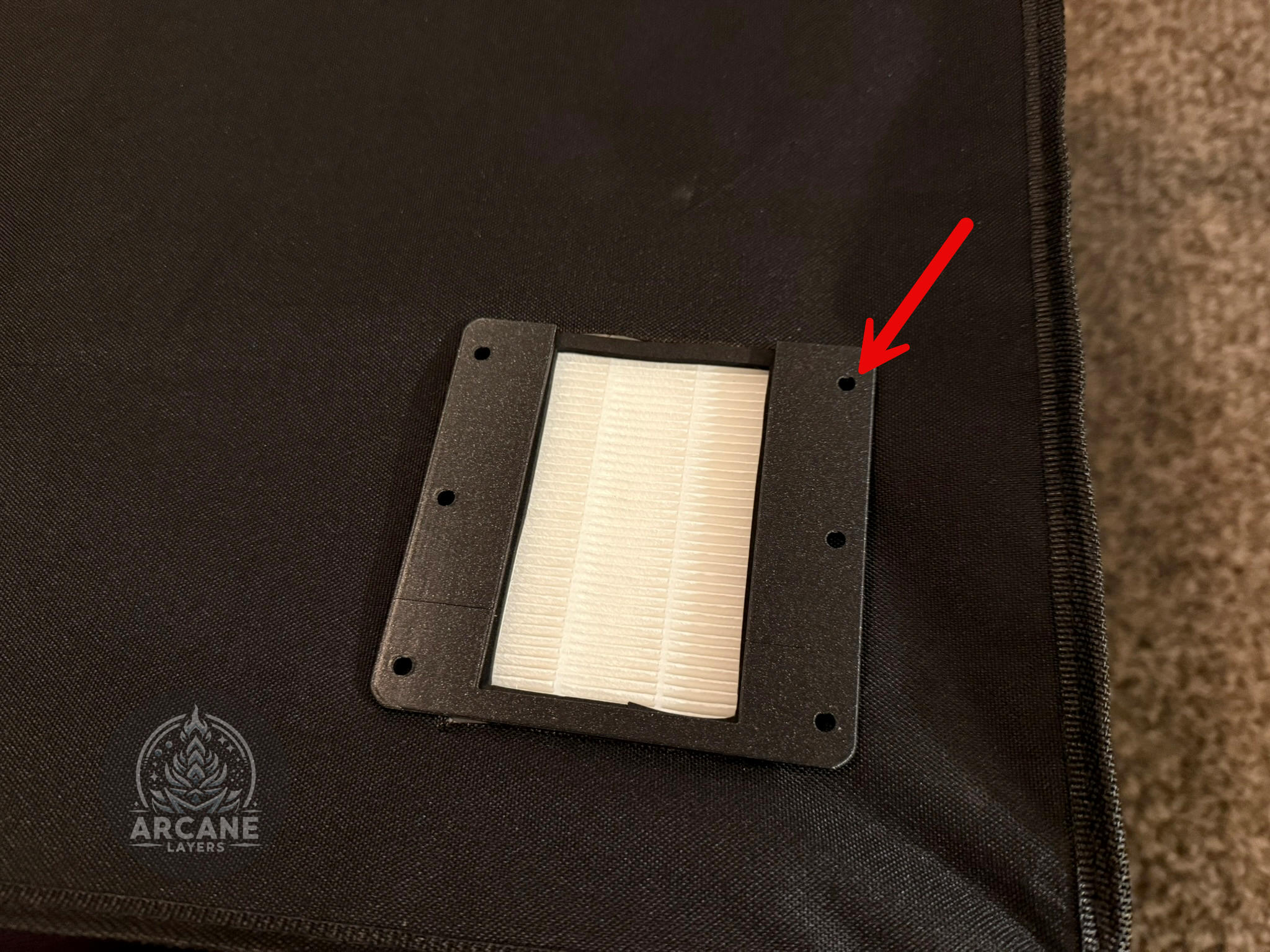
Use a nail, something similar to punch the holes where they need to go.
-
Screw through the main piece, through the holes, into the backplate and nuts.
The Final Product
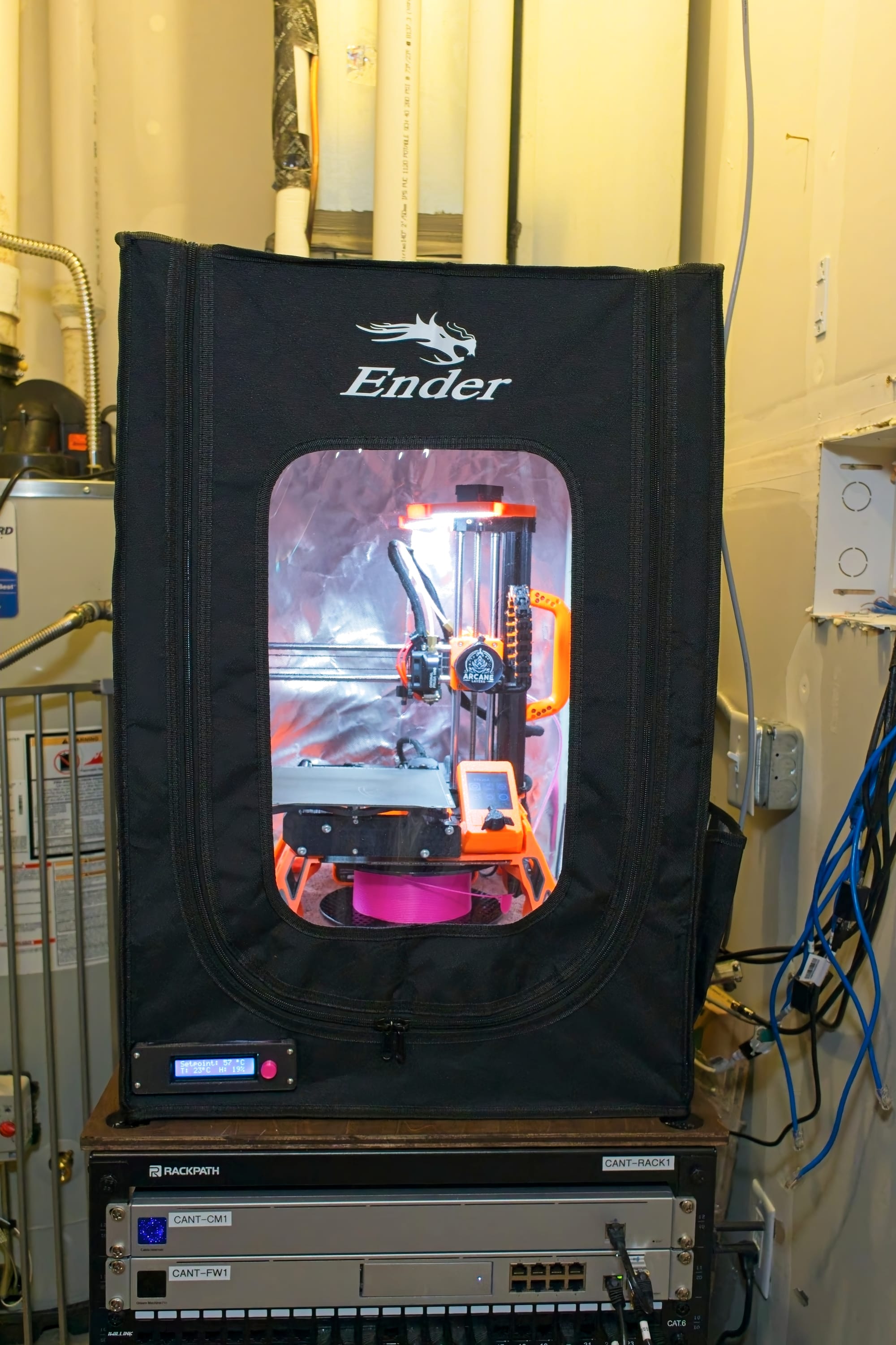
Run the wires throughout your enclosure to connect the controller to power, and the fan to the controller, once done, you should have an amazing 3D print enclosure for all of your future projects, enjoy!
Bonus Print!
Left over materials? Here's my suggestion.
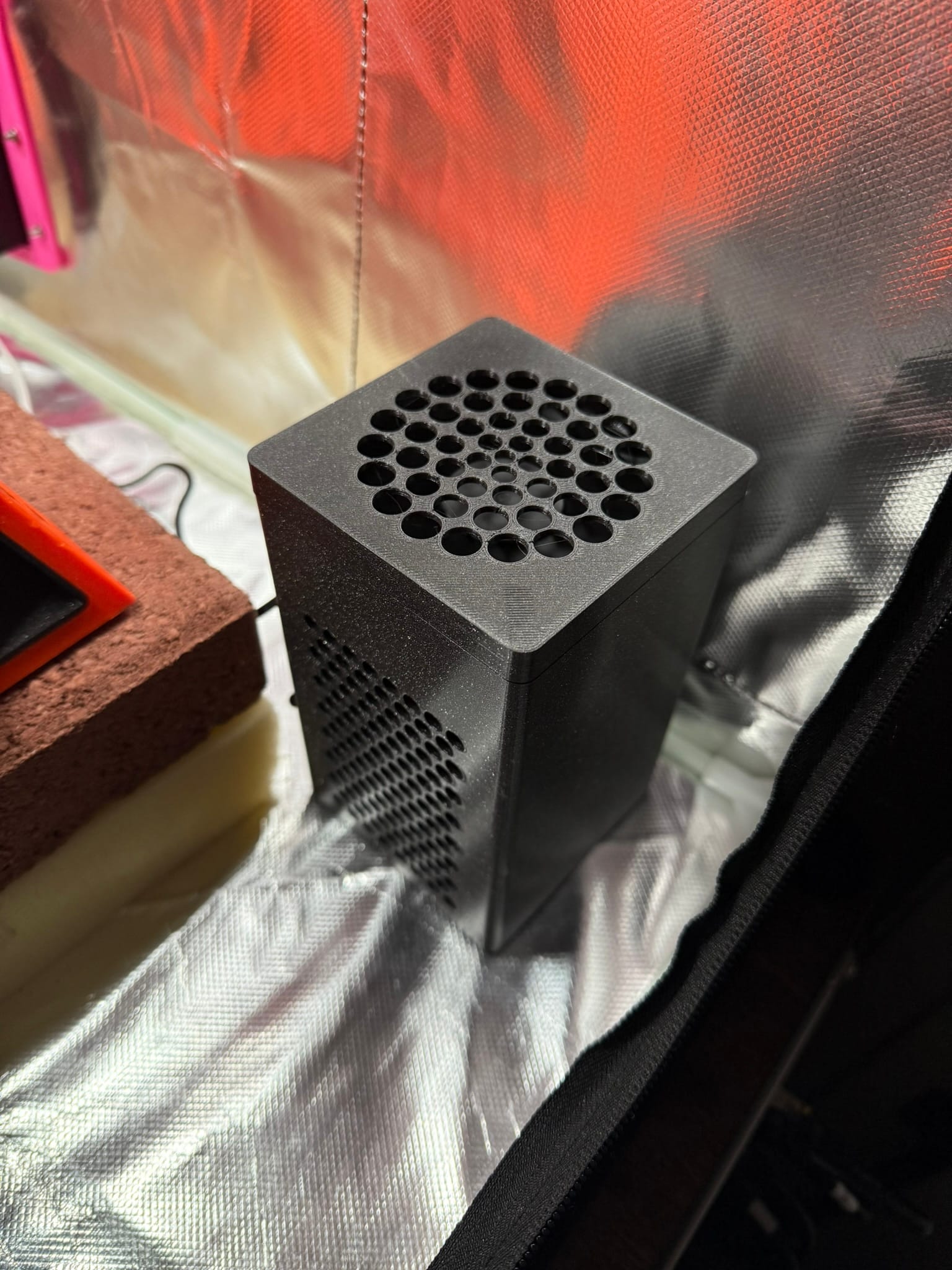
You may notice after assembly that you have extra filters, power supplies, fans, and barrel adapters. I would highly recommend using those to create a small air purifier to put into the enclosure which will further help filter the air. I'd recommend picking up some carbon pellets and printing this air purifier model by Michael Whitley. Pour the carbon pellets between the filters and now you have an air purifier which can purify the inside of the enclosure!
